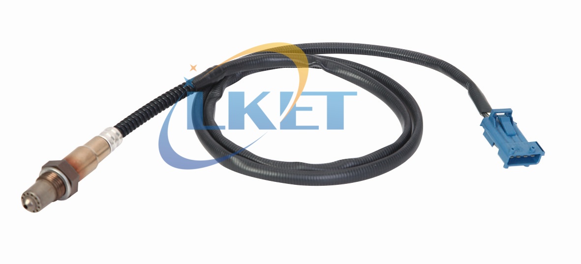
How to Diagnose a Faulty Oxygen Sensor
1. Identifying Failure Symptoms
A. Observable Vehicle Behaviors
-
Check Engine Light (CEL) Illumination:
Persistent CEL with diagnostic trouble codes (DTCs):P0130-P0167(Circuit malfunctions)P0171/P0174(System too lean)P0420/P0430(Catalyst efficiency below threshold)
Note: 68% of P0420 codes originate from faulty rear O₂ sensors (Bosch Technical Bulletin 2021).
-
Fuel Economy Degradation:
Abnormal fuel consumption increase (≥15% over baseline). Example:
2.5L Toyota Camry hybrid: Normal 5.4 L/100km → Faulty O₂: 6.8 L/100km -
Performance Issues:
- Rough idle (RPM fluctuation >±200 rpm)
- Hesitation during acceleration
- Engine stalling after cold start
-
Exhaust Anomalies:
- Black soot at tailpipe (excess fuel)
- Rotten egg odor (catalyst converting H₂S due to rich mixture)
B. Emission Test Failures
| Gas | Healthy Level | O₂ Sensor Failure |
|---|---|---|
| HC | < 100 ppm | > 250 ppm |
| CO | < 0.5% | > 3.0% |
| NOx | < 350 ppm | > 800 ppm |
| Data per EPA Tier II Bin 5 standards |
2. Diagnostic Procedures
A. Visual Inspection
-
Sensor Damage:
- Impact cracks in ceramic element
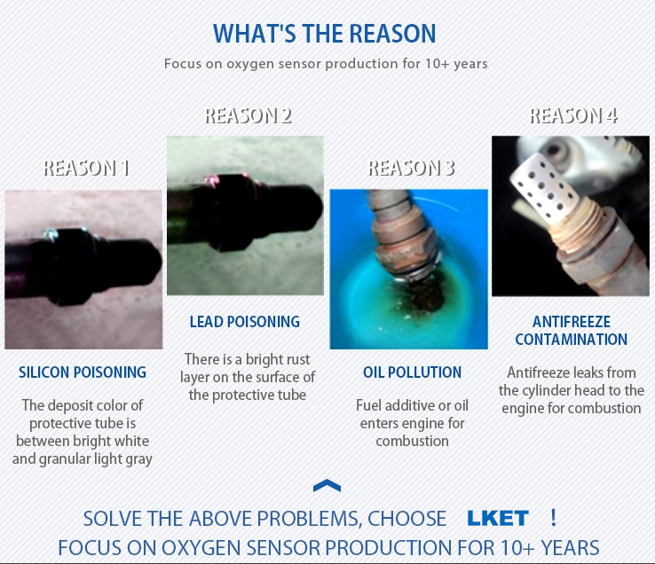
- Contamination:
▪ Oil ash (white/gray deposits): Valve seal leaks
▪ Silica glaze (shiny coating): Coolant contamination
▪ Red rust: Unburned fuel
-
Wiring Harness:
▪ Chafing against exhaust components
▪ Melted insulation (>120°C indicates proximity failure)
B. Electrical Testing (Multimeter Required)
- Heater Circuit Check:
Disconnect sensor → Measure resistance between heater terminals: ✓ Normal: 5–25 Ω (at 20°C) ✘ Open circuit: ∞ Ω ✘ Short circuit: <3 Ω - Reference Voltage Verification:
Backprobe signal wire → Key ON/engine OFF: Should read 450mV±50mV
C. Dynamic Signal Analysis (Oscilloscope Required)
Normal Operation:
- Upstream sensor: 0.1–0.9V rapid cross-counts (>8 cycles/10 sec at 2000 rpm)
- Downstream sensor: Steady voltage (0.45–0.7V)
Failure Patterns:
| Fault Type | Upstream Signal | Downstream Signal |
|---|---|---|
| Slow response | Frequency <5Hz | N/A |
| Stuck lean | Fixed at 0.1–0.2V | Fixed <0.3V |
| Stuck rich | Fixed at 0.8–0.9V | Fixed >0.7V |
| Shorted heater | Erratic spikes | Erratic spikes |
D. Fuel Trim Interpretation (Scan Tool Data)
| Trim Value | Healthy Range | Fault Indication |
|---|---|---|
| Short-Term FT | ±5% | >±10% continuously |
| Long-Term FT | ±8% | >±15% continuously |
LTFT >10% for >2 drive cycles = Sensor degradation (GM TSB #07-06-04-006)
3. Sensor-Specific Test Protocols
A. Wideband Sensors (LSU 4.2/LSU 4.9)
- Connect diagnostic tool → Force open loop mode
- Introduce artificial vacuum leak:
✓ Expected: AFR >16.0:1
✘ Fault: AFR fails to rise - Measure pump current:
Normal transition 0–20mA when AFR swings 14.7→18.0
B. Titania Sensors (Rare in post-2005 vehicles)
- Resistance test:
Normal operation:
Rich mixture: ~1 kΩ
Lean mixture: ~20 kΩ
C. Smart Sensors (CAN-bus Integrated)
- ECU handshake verification:
Terminal 6 voltage: 0V = No communication - DTC Uxxxx codes indicate CAN communication failure
4. Failure Root Causes
| Cause | Impact on Sensor Lifespan | Preventive Measures |
|---|---|---|
| Thermal cycling | Cracked ceramic element | Avoid cold engine WOT |
| Contaminants | Poisoned electrode | Fix oil/coolant leaks ASAP |
| Voltage spikes | Burned heater coil | Check alternator output |
| Mechanical stress | Broken wiring | Use OEM-spec sensor sockets |
Manufacturer-Specific Vulnerabilities
- Toyota Denso sensors: Prone to silicone poisoning from RTV sealants
- Bosch LSU 4.2: Water intrusion via connector seals (TSB 01-2020)
- Delphi NTK: Exhaust condensation corrosion in short-trip driving
5. Replacement Guidelines
When to Replace (Hard Rules):
- Heater circuit resistance <3Ω or >25Ω
- Signal voltage deviation >±0.1V from reference at KOEO
- Cross-count rate <50% of specification
- History codes reappear within 200 miles of reset
Installation Best Practices:
- Apply copper-free anti-seize ONLY to threads (NGK TA201)
- Torque to manufacturer spec (Typical 40±5 N·m)
- Reset ECU adaptives after replacement
- Road test ≥15 mins with varied load/RPM
Sensor Life Expectancy
| Vehicle Type | Avg. Service Life | Failure Mileage Deviation |
|---|---|---|
| Gasoline N/A | 120,000 km | ±20,000 km |
| Turbo GDI | 80,000 km | ±15,000 km |
| Hybrid | 160,000 km | ±30,000 km |
| Diesel w/DPF | 100,000 km | ±18,000 km |
6. Case Study: 2018 Toyota Prius P0171
Initial Symptoms:
- CEL with P0171
- LTFT: +23% at idle
- Fuel economy: 4.3 L/100km → 5.8 L/100km
Diagnostic Steps:
- Oscilloscope test: Upstream signal flatlined at 0.12V
- Heater circuit test: 6.8Ω (within spec)
- Voltage reference: 0.4V (acceptable)
- Visual inspection: Silica-contaminated tip
Root Cause:
Coolant leak from cylinder head → Sensor poisoned by silicate compounds
Repair:
- Replaced O₂ sensor (DENSO 234-9046)
- Repaired head gasket
- Reset ECU adaptations
Result:
- LTFT stabilized at +4%
- Fuel economy restored to 4.2 L/100km
7. Advanced Tools & Special Cases
Diagnostic Tool Minimum Requirements:
- Ability to display O₂ sensor voltage at ≥50 samples/sec
- Mode $06 diagnostics for catalytic converter efficiency testing
Atypical Sensor Failures:
- False lean signal in modified vehicles: Requires wideband calibration after cat removal
- EMI-induced noise: Check spark plug wires resistance (<5kΩ/ft)
- Ground offset errors: Verify ECU ground path resistance <0.1Ω
Safety Precautions:
- Never test sensors at >150°C exhaust temp (sensor damage risk)
- Disable ignition before probing circuits in DIS systems
- Use CAT III-rated multimeters for hybrid vehicle testing
What Does a Thermostat Do in a Car?
Why heater valve control is important?
Related Article