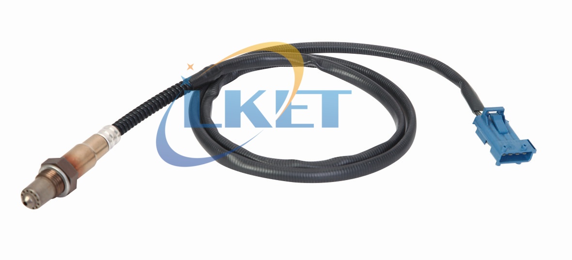
Professional Guide to Oxygen Sensor Installation: Standardized Operation is the Core of Performance Assurance
I. Preparation Phase: Dual Assurance of Tools and Safety
Installation begins with thorough preparation, focusing on specialized tools and safety protection. A dedicated oxygen sensor socket wrench is an indispensable tool. Its side-notch design accommodates the wiring harness, ensuring even force distribution. A torque wrench guarantees precise tightening, effectively preventing thread damage or probe breakage due to improper force. Additionally, specialized anti-seize compound (non-metallic), thread cleaning tools, and an OBD diagnostic scanner are required.
For safety, operation must be performed on a completely cool vehicle to avoid burns from hot exhaust components; safety glasses and gloves must be worn to prevent contact with rust debris and grease.
II. Removing the Old Sensor: Orderly Operation to Prevent Damage
Removal must follow a standardized procedure: First, disconnect the electrical connector. Pulling directly on the wiring harness is strictly prohibited; the connector must be unclipped and then pulled apart. For severely rusted sensors, apply penetrating oil and let it soak for at least 15 minutes. Finally, use the dedicated socket, employing a "slow rocking + counterclockwise turning" method for removal. If resistance is high, alternate between tightening and loosening to break the rust bond, avoiding any use of brute force.
III. Installing the New Sensor: Precision and Attention to Detail Determine Success
Installation of the new sensor must strictly follow a three-step rule:
- Base Cleaning: Thoroughly clean the installation hole's threads of all rust and debris using a tap or thread chaser, ensuring the new sensor screws in without obstruction.
- Thread Treatment: Apply a small amount of specialized anti-seize compound evenly to the new sensor's threads (avoid excess). This prevents corrosion and facilitates future removal.
- Staged Tightening: First, hand-tighten the sensor until it can no longer be turned by hand, confirming the threads are properly aligned. Then, use a torque wrench to tighten to the specified torque (typically 30-50 N·m). This step completely avoids the risks of stripped threads or cracked sensor housings.
Finally, route the wiring harness properly, securing it in the original factory clips away from high-temperature areas and moving parts, and ensure the electrical connector is fully engaged and locked.
IV. Post-Installation Verification: Data Stream Testing Completes the Process
Validation is required after installation: First, use the diagnostic scanner to clear any historical fault codes. Then, start the engine and allow it to reach operating temperature. Read the upstream oxygen sensor data stream. Under normal conditions, the signal voltage should fluctuate rapidly between 0.1V and 0.9V, and the Short-Term Fuel Trim (STFT) should stabilize. If the data meets these standards, it indicates a successful installation and proper sensor function.
Summary
Oxygen sensor installation is a professional operation that combines technical specifications and detailed management. Every step—from selecting specialized tools and thread preparation, to precise torque control and final data verification—must strictly adhere to technical standards. Only in this way can the long-term stable operation of this precision component be ensured, truly realizing its core value in optimizing fuel consumption, controlling emissions, and protecting the engine.
What about smart thermostats?
Winter Car Heater Not Working? The Heater Valve is the Key!
Related Article