Automotive Oxygen Sensor Function, Troubleshooting and Follow-Up Guide - A Core Component for Improving Fuel Ratio and Reducing Tailpipe Emissions
- Definition and Core Role
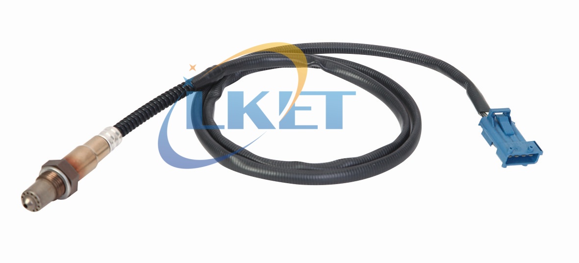
Automotive Oxygen Sensors are electronic devices installed in the vehicle exhaust system for real-time detection of oxygen content in the tailpipe gas, and feedback of data to the Engine Control Unit (ECU). In order to optimize the Air-Fuel Ratio (Air-Fuel Ratio), to ensure efficient combustion, reduce emissions, and comply with environmental regulations (such as the National Six, European standards)
- Core Functions
2.1 Monitoring Oxygen Content
The oxygen sensor is installed in the engine exhaust system (usually located in front of and behind the three-way catalytic converter) and detects the oxygen concentration in the exhaust in real time.
Working principle: The sensor generates a voltage signal (usually 0.1V-1V) proportional to the oxygen concentration by measuring the partial pressure of oxygen.
High voltage (close to 1V): High oxygen concentration indicates a lean mixture (more air, less fuel).
Low voltage (close to 0.1V): low oxygen concentration indicates that the mixture is too rich (more fuel, less air).
2.2 Closed Loop Fuel Control
The ECU dynamically adjusts the fuel injection volume according to the feedback signal from the oxygen sensor so that the mixture is always kept near the theoretical air-fuel ratio (14.7:1).
Effects: Reduces emissions: Reduces the generation of carbon monoxide (CO), hydrocarbons (HC) and nitrogen oxides (NOx).
Improves fuel economy: Avoids fuel waste and reduces fuel consumption.
Protect the three-way catalytic converter: Ensure that the catalytic converter works at optimal efficiency and extends its service life.
2.3 Diagnose engine faults
The signal of the oxygen sensor is an important parameter of the engine fault diagnosis system (OBD).
Fault Determination: If the sensor signal is abnormal for a long time (such as no change in voltage or delayed response), it may indicate sensor failure, injector blockage, air flow meter failure, etc. The ECU will record fault codes (such as “no change in voltage” or “delayed response”).
The ECU will record the fault code (e.g. P0131, P0135) and light up the malfunction lamp (MIL).
- Classification and Characteristics of Oxygen Sensors
Sensitivity and Fast Response: It can accurately and quickly measure the oxygen concentration, and is very sensitive to the change of oxygen concentration.
Good stability: It has high stability and anti-interference ability, and can maintain stable performance in complex environment.
Accurate measurement: the corresponding oxygen concentration is calculated through the principle of chemical equilibrium, which can accurately monitor the concentration of oxygen in the exhaust and feed back to the control unit.
Working temperature requirement: Its characteristics can only be fully realized at high temperature (end reaching over 300°C) to output voltage, and it reacts the fastest to the change of mixture at about 800°C.
Wide range of applications: widely used in various types of combustion atmosphere control, such as coal combustion, oil combustion, gas combustion and other furnace atmosphere control, as well as automotive engines in the electronic control of fuel injection system.
Simple structure, easy maintenance: relatively simple structure, easy to use, low maintenance costs
- Working Principle
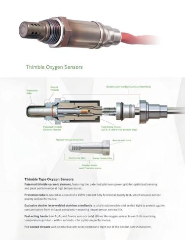
The core element of the oxygen sensor is the zirconium oxide tube, which is a solid electrolyte with porous platinum electrodes and alumina protective layer covering its inner and outer surfaces, the inner surface is connected with the atmosphere, and the outer surface is in contact with the exhaust gas.
When the exhaust gas is in contact with the outer surface of the zirconium tube, the residual oxygen in the exhaust gas contacts the zirconium oxide through the platinum electrodes and the alumina protective layer, and the potential difference between the inside and outside of the zirconium tube occurs due to the difference in the concentration of oxygen at a certain high temperature. When in concentrated combustion, the oxygen concentration in the exhaust gas decreases, and the output voltage of the oxygen sensor rises above the reference voltage. In dilute combustion, the oxygen concentration in the exhaust gas increases, and the output voltage of the oxygen sensor drops below the reference voltage.
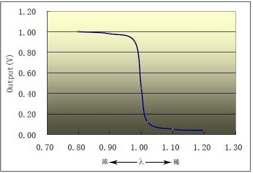 |
Theoretical air-fuel ratio: A/F=14.7:1 (λ=1)
Strong mixture: When the actual air-fuel ratio is less than the theoretical air-fuel ratio, the mixture is called a rich mixture.
Dilute mixture: When the actual air-fuel ratio is greater than the theoretical air-fuel ratio, the mixture is called dilute mixture.
When the mixture becomes thicker, i.e. the concentration of oxygen content in the exhaust gas decreases (λ<1), the output voltage signal of the oxygen sensor will be close to 1V.
When the mixture becomes thin, i.e. the concentration of oxygen content in the exhaust gas increases (λ>1), the output voltage signal of the oxygen sensor will be close to 0V.
- Product Details
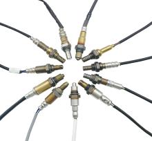
- Product Installation
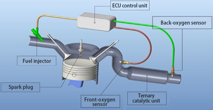
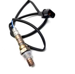
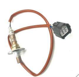
Front oxygen sensor and rear oxygen sensor are installed in different positions and functions.Taking the three-way catalytic as the boundary, the one before the three-way catalytic is the front oxygen sensor, and the one after the three-way catalytic is the rear oxygen sensor.
The front oxygen sensor is used to detect the air-fuel ratio of different engine conditions, while the computer adjusts the fuel injection and calculates the ignition time according to this signal.
The rear oxygen sensor feeds the oxygen content behind the three-way catalytic converter to the engine computer to detect whether the three-way catalytic converter is working properly. If the data detected by the front oxygen sensor and the rear oxygen sensor are the same, the three-way catalytic has failed.
- Typical Failure Manifestations
7.1 Increased fuel consumption, decreased power, exhaust odor
7.2 Engine malfunction light is on (e.g. P0420 catalytic converter is inefficient)
- Detection Methods
8.1 Use OBD-II scanner to read the real-time data stream (observe whether the voltage fluctuation is normal or not).
8.2 Test the heating circuit resistance with a multimeter (usually 4-6Ω).
- Replacement and Maintenance Guide
9.1 Disconnect the negative terminal of the battery and remove the sensor plug.
9.2 Use a special oxygen sensor wrench (to avoid damaging the threads).
9.3 Apply anti-seize when installing new sensor and tighten according to torque specification.
Automotive Sensors: Functions, Types, Working Principles and Specific Locations Explained
Related Article